(T4)

| Go List | PASS | |||||||||||||||||||||||||||||||||
| FAIL | ||||||||||||||||||||||||||||||||||
| Power Good Signal (POK, or P_GOOD) | N/T | |||||||||||||||||||||||||||||||||
| N/A | ||||||||||||||||||||||||||||||||||
| Model : | Reference | |||||||||||||||||||||||||||||||||
| 1. Equipment : | ||||||||||||||||||||||||||||||||||
| (1) AC Source : Chroma 6530 | ||||||||||||||||||||||||||||||||||
| (2) DC Load : Chroma 63102/63103 | ||||||||||||||||||||||||||||||||||
| (3) Oscillo | ||||||||||||||||||||||||||||||||||
| (A) DC So | ||||||||||||||||||||||||||||||||||
| 2. Test Condition : | ||||||||||||||||||||||||||||||||||
| (1) AC Input Voltage : Min. and Max. of Input Voltage | ||||||||||||||||||||||||||||||||||
| (2) Input Frequency : 60Hz /50Hz | ||||||||||||||||||||||||||||||||||
| (3) Load Condition : LD1 & LD2 | ||||||||||||||||||||||||||||||||||
| (4) Temperature :Room Ambient Temperature | ||||||||||||||||||||||||||||||||||
| (5) Wavefrom Requirement : 12V/PG | ||||||||||||||||||||||||||||||||||
| 3. Spec : | ||||||||||||||||||||||||||||||||||
| The power good signal (TTL compatible) shall be provided to indicate normal operating conditions of the power supply. The power good signal will be asserted (low state) during power up until the +5VDC outputs are within the regulation range defined in Section 3.2.1 The electrical and timing characteristics of the power good signal, are shown in Table 7 and Figure1: Power Supply Timing. PWR_OK should be de-asserted to a low state when any of the +12 VDC, +5 VDC, or +3.3 VDC output voltages falls below its under voltage threshold, or when mains power has been removed for a time | ||||||||||||||||||||||||||||||||||
| The output will be an open collector/drain type. It will be capable of driving the output below 0.4V with a load of | ||||||||||||||||||||||||||||||||||
| up to 10 mA. | ||||||||||||||||||||||||||||||||||
| The output will have an internal pull-up resistor of 1K between the output and either Standby or +5VDC. | ||||||||||||||||||||||||||||||||||
| Parameter Description | Min | Typ | Max | Units | ||||||||||||||||||||||||||||||
| Power Good Events | ||||||||||||||||||||||||||||||||||
| AC Main Power Loss | Yes | Yes/No | ||||||||||||||||||||||||||||||||
| Fan Failure | No | Yes/No | ||||||||||||||||||||||||||||||||
| Over Temperature | No | Yes/No | ||||||||||||||||||||||||||||||||
| 4. Test Result : | PASS | |||||||||||||||||||||||||||||||||
| Power Good Signal Level | Load Condition | Test Result | Spec | |||||||||||||||||||||||||||||||
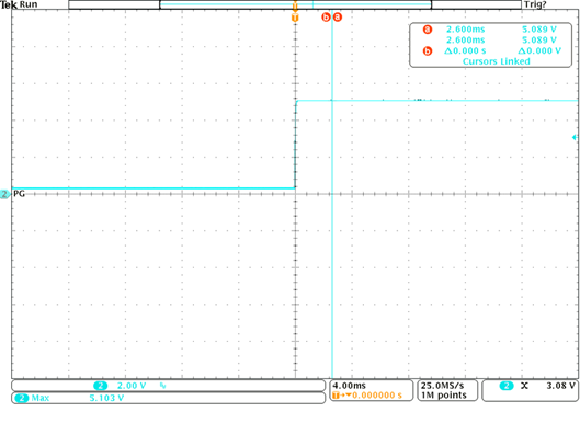
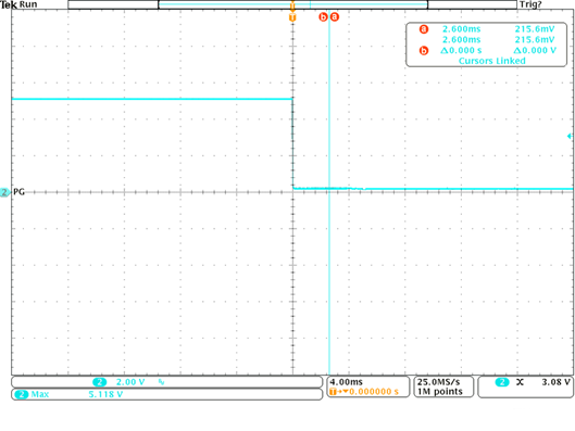
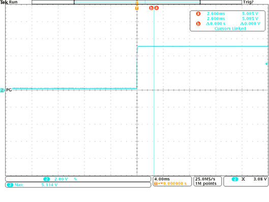
| Hi Level | 90VAC | LD1 | 5.089V | Power Good signal will have an internal pull-up resistor of 1K between the output and Standby | ||||||||||||||||||||||||||||||
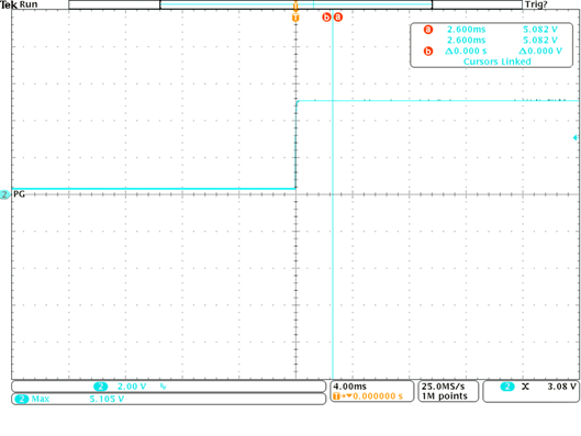
| 264VAC | 5.082V | |||||||||||||||||||||||||||||||||
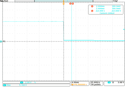
| Low Level | 90VAC | 0.303V | < 0.4V | |||||||||||||||||||||||||||||||
| 264VAC | 0.3V | |||||||||||||||||||||||||||||||||
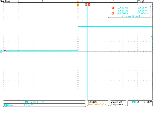
| Hi Level | 90VAC | LD2 | 5.096V | Power Good signal will have an internal pull-up resistor of 1K between the output and Standby | ||||||||||||||||||||||||||||||
| 264VAC | 5.095V | |||||||||||||||||||||||||||||||||
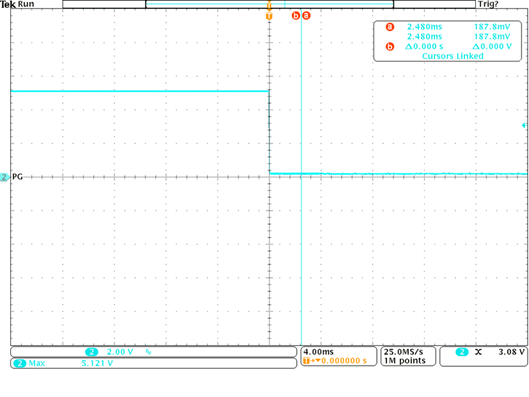
| Low Level | 90VAC | 0.215V | < 0.4V | |||||||||||||||||||||||||||||||
| 264VAC | 0.187V | |||||||||||||||||||||||||||||||||
| Test Item | Test Result | Pass/Fail | Spec | |||||||||||||||||||||||||||||||
| Over Current Protection | Low | Pass | Low | Refer to OC | ||||||||||||||||||||||||||||||
| Over Voltage / Under Voltage Protection | Low | Pass | Low | Refer to OV | ||||||||||||||||||||||||||||||
| DC Outputs
Pre Warning Time (T4) |
Pass | Pass | Power Good signal must be driven low at least 1ms before any of the outputs go out of regulation | Refer to T4 | ||||||||||||||||||||||||||||||
| 90V 60Hz PS_ON ON Load1 | 90V 60Hz PS_ON OFF Load1 | |||||||||||||||||||||||||||||||||
|
|
|
|||||||||||||||||||||||||||||||||
| 264V 50Hz PS_ON ON Load1 | 264V 50Hz PS_ON OFF Load1 | |||||||||||||||||||||||||||||||||
|
|
|
|||||||||||||||||||||||||||||||||
| 90V 60Hz PS_ON ON Load2 | 90V 60Hz PS_ON OFF Load2 | |||||||||||||||||||||||||||||||||
|
|
|
|||||||||||||||||||||||||||||||||
| 264V 50Hz PS_ON ON Load2 | 264V 50Hz PS_ON OFF Load2 | |||||||||||||||||||||||||||||||||
|
|
|
|||||||||||||||||||||||||||||||||